In this article, we will be focusing on multi-meter testing/measuring phone parts with the instrument under consideration. While working on GSM phones, whether on the card level parts, the small parts or the big parts, you will at one time or the other need to carry out testings and measurements for the purpose of troubleshooting problems in an attempt to fix stuff.
The multi-meter testing/measuring phone parts is indispensable to the GSM expert technician in finding faults and proffering solutions. The lack of knowledge in this area can result in inability to fix phone problems or even damage them by doing trial by error repairs. With the help of the multi-meter the work becomes easier.
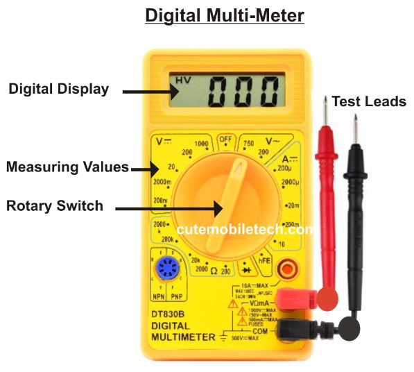
Whats A Multi-Meter?
A multi-meter as the name implies, is an electronic instrument used in measuring and testing electrical or electronic equipment and components. There are different types of multi-meters, the ones you will familiarize with at this job is the digital and analogue multi-meters. The digital multi-meter utilizes digital display on the LCD screen to display values.
On the other hand, the analogue version utilizes a needle-like pin which moves from left to right while showing readings or testing result over a range of values/readings. Most G.S.M technicians prefer the digital multi-meter because it appears to be better and easier to cope with. While using your digital multi-meter, be sure to have a good battery voltage, otherwise you will have false readings.
Parts of A Multi-Meter
As we major on multi-meter testing/measuring phone parts, we are going to be focusing on that alone. Meanwhile you may research on that if you please. The digital multi-meter has two test leads namely the positive and the negative test leads. Usually placed on the surface for testing to take readings or carry out testings before, during or after repairs.
There is the knob that is also used for changing measurement mode, whether to test battery voltage, test resistance in ohms, check continuity, shorts or open circuits et ceteral.
Commonly Measured Parts During Phone Repairs
- Resistors
- Capacitors
- Diodes
- Transistors
- LEDs
- Current/votage
- Continuity
- Shorts or open circuit
Multi-Meter Testing/Measuring Phone Parts
Resistors
The resistors are the most common electronic components you will find on a mobile phone as they are very important in their role; they resist the flow of current to a given value and can be found just in any section, whether in the power or the network section. Resistors don’t short but can be open or drop/increase in value under certain conditions.
You can measure the resistance value by switching to the Ohms mode with the sign (Ω). Once value is taken, you will be able to replace the faulty resistor with the exact value for proper functioning. Read more on resistors and other components parts below in another article here.
Capacitors
Capacitors are great components in mobile phones PCBs that helps in filtering and stabilization of current voltage. In mobile phones, you will find both polarized and non-polarized capacitors. When working with the polarized ones, you must give attention to the negative and the positive terminals. when changing capacitors, you should consider using exact or equivalent values when they are shorted.
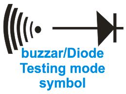
To measure the capacitor, the capacitance meter is used. Most fixes you will engage in is that of experiencing a capacitor short. A capacitor that is faulty can be spotted immediately when it gives continuity sound in buzzer mode which it shouldn’t. To test if a capacitor is okey, you can check for continuity sound in buzzer mode or set your meter at range 2000 Ohms. If you notice an increase in value, then its okay. When also set at 20 in DCV mode and you notice a rapid decrease in value, that’s an okay sign.
Diodes
Diodes have both the negative terminal referred to as cathode and the positive terminal called anode. It allows flow of current in a given direction (one direction) and sometimes in opposite direction depending on the need or use.
The simple way to test for diode is in buzzer mode. When the test leads are place on the anode and cathode, it shouldn’t buzz, if it buzzes, then that’s a sign of short and should be replaced. You would familiarize with zener and rectifier diode while dealing in phone repairs. diode can be found in the power section on the PCB mostly and are black in color.
Transistors
Though somewhat technical, its typically an integration of two or more diodes in to one components IC chip. The terminals or points can be measured in accordance based on the arrangement to detect a short or fault. They can be given same approach in testing diodes. There are different types transistors you will come across in the electrical electronics space if you are keen about researching them, for example the NPN and the PNP transistors and their classifications etc.
LEDs
Multi-meter testing/measuring phone parts like LEDs is possible. LEDs are the light emmiting diodes. They are use for illuminating Screens of mobile phones and also serves as camera flash light. They can also be tested for fault in buzzer mode by placing the both test leads in opposite negative and positive directions to see if it lights up. If it doesn’t light up, then the LED is bad.
Current/Voltage
While repairing phones, you will also measure current voltage supply to ascertain the value of flow of electricity in the PCB. The multi-meter helps to give values so you can easily know where to concentrate on. If for instance you place the two test leads on the battery VBAT terminal and the GND and you get a 2.3 Volt reading instead of 3.5 or a little more, then you realize a drop in supply which tells you to check for other components that might need troubleshooting to fix the problem.
You can also use the multi-meter to check the current voltage of your phone battery by placing both test leads on the corresponding positive and negative interface set at 20 DCV mode.
Continuity
The multi-meter can also be used to test the continuity in a circuit, or of a wire or any electricity conducting material to check for broken path so as to apply jumpers or fixes where necessary.
Shorts/Open
With the multi-meter, shorts and open circuits are easily detected. When you gain expertise detecting short or open circuits which defines bridges or disconnection due to faults, you will be able to deal with most power related problems and others you will come across while you are at this job.
More Testings
While trying to work things out, it better to know the resistance value of some commonly affected components like the mouthpiece, earpiece and ringers to avoid the trial by error approach.
Testing Mouthpiece, Earpiece And Ringers
The resistance value should range between 600 to 1800 Ohms for mouthpiece. Resistance for earpiece should go around 25 to 35 Ohms while the ringer should range between 8 to 9 Ohms.
Note that a high resistance will result in limiting the flow of current thus causing low or moderate sound and a low resistance will result in more current flow and thus high volume or sound out put. Also when the resistance value of a mouthpiece for example goes as low as 100 Ohms instead of between 600 and 1800 Ohms then the receiver on the other end will find it difficult to hear and vise versa.
While testing mouthpiece in buzzer mode, if it gives sound, then its damaged. While testing an earpiece or speaker in buzzer mode it they both give sound they are good, but you still need to check their resistance and check also if the sound is not distorted because their could be internal damage et ceteral.
Related Articles:


I like this page
Thanks for your effort. Please I’m having problem with my button itel402 display. What happen was that it develop the fault In the power button in such a way that it power on automatically immediately when you put ba3 so I try rehoting the power ic but unfortunately it went blank it doesnt display anything. Please any help
U shd not hv reworked d pwr IC, U ought to hv troubleshoot for pwr track short. Now u need to reball the IC for under led spill.